
Saturday, 30 April 2016
Thursday, 28 April 2016

Wednesday, 27 April 2016
Helicopters Engine
Powerplant
The two most common types of engines used in helicopters are the reciprocating engine and the turbine engine.
Reciprocating engines, also called piston engines, are generally used in smaller helicopters. Most training helicopters use reciprocating engines because they are relatively simple and inexpensive to operate. Turbine engines are more powerful and are used in a wide variety of helicopters. They produce a tremendous amount of power for their size but are generally more expensive to operate.
Reciprocating Engine
The reciprocating engine consists of a series of pistons connected to a rotating crankshaft. As the pistons move up and down, the crankshaft rotates. The reciprocating engine gets its name from the back-and-forth movement of its internal parts. The four-stroke engine is the most common
type, and refers to the four different cycles the engine undergoes to produce power.

The arrows indicate the direction of motion of the
crankshaft and piston during the four-stroke cycle
When the piston moves away from the cylinder head on the intake stroke, the intake valve opens and a mixture of fuel and air is drawn into the combustion chamber. As the cylinder moves back toward the cylinder head, the intake
valve closes, and the fuel/air mixture is compressed. When compression is nearly complete, the spark plugs fire and the compressed mixture is ignited to begin the power stroke. The rapidly expanding gases from the controlled burning of the fuel/air mixture drive the piston away from the cylinder head, thus providing power to rotate the crankshaft. The piston then moves back toward the cylinder head on the
exhaust stroke where the burned gases are expelled through
the opened exhaust valve. Even when the engine is operated
at a fairly low speed, the four-stroke cycle takes place several hundred times each minute. In a four-cylinder engine, each cylinder operates on a different stroke. Continuous rotation of a crankshaft is maintained by the precise timing of the power strokes in each cylinder.
Turbine Engine
The gas turbine engine mounted on most helicopters is made up of a compressor, combustion chamber, turbine, and accessory gearbox assembly. The compressor draws filtered air into the plenum chamber and compresses it. The compressed air is directed to the combustion section through discharge tubes where atomized fuel is injected into it. The fuel/air mixture is ignited and allowed to expand. This
combustion gas is then forced through a series of turbine wheels causing them to turn. These turbine wheels provide power to both the engine compressor and the accessory gearbox. Power is provided to the main rotor and tail rotor systems through the freewheeling unit which is attached to the accessory gearbox power output gear shaft. The combustion gas is finally expelled through an exhaust outlet.

Many helicopters use a turboshaft engine to drive the main transmission and rotor systems. The main difference between a turboshaft and a turbojet engine is that most of the energy produced by the expanding gases is used to drive a turbine rather than producing thrust through the expulsion of exhaust gases.
Tuesday, 26 April 2016
ENGINE ASSEMBLY
Introduction. After all machining procedures on the cylinder block have been performed correctly, the engine is ready for reassembly. Let's not forget that while assembling the
engine, specifications are still just as important as they were during the repair of the individual components. Remember also that dirt is harmful to the engine. Even the slightest particle is abrasive and can shorten the life of the engine by many miles or hours of operation. With the above facts firmly in mind, you are ready to assemble the engine with which you have taken so much care to repair properly.
CRANKSHAFT INSTALLATION
1. Preassembly
To ensure proper lubrication of moving parts, all bearings, shafts, and contact surfaces must be lubricated before installation and engine oil should be used for this. Never reuse old gaskets and seals. Once a seal has been removed, it is damaged and damaged seals can be a source of leakage that results in premature wear and damage to moving parts. During assembly of the engine, almost every nut and bolt to be tightened has a specific torque. These torque specifications are listed in the TM and must be strictly adhered to. Over-tightened bolts and nuts will result in excess stress on the metal, and under-tightened nuts and bolts will result in oil or vacuum and pressure leaks. Basically, all engines are assembled in the same manner. This study unit provides a basic knowledge of assembly, and your TM will provide you with details of the particular engine you will be rebuilding or repairing.
2. Installing the Crankshaft
The crankshaft is the first component that must be installed if the engine is to be assembled in a logical order. This may vary depending on the type of engine you are rebuilding. Before actually placing the crankshaft in the engine, position the engine block with the crankshaft side up. Install the rear main bearing seals (the rear main bearing is the only main bearing with seals). These seals are installed in grooves provided to the rear of the point from which the rear main journal of the crankshaft rests in the engine and on the groove provided in the rear main bearing cap. There are various types of seals (felt packing, neoprene, encased, etc.). common types of rear seals.

Encased seal

Two-piece seal
The encased seal is installed after the crankshaft has been installed in the engine. Care must be exercised to ensure that the seal is driven into the block evenly, or damage may result. To install the crankshaft, first install the upper halves of the crankshaft's main bearings in the engine block, and the lower halves in the main bearing caps. Make sure the bearing halves are thoroughly cleaned and, as mentioned previously, all friction surfaces coated with engine oil. The bearing tangs must fit into the slots in the cap and block evenly, or they will be flattened. The tang is provided to prevent the bearing from turning with the crankshaft. If a bearing turns, it will cause almost immediate damage.

Installing main bearing halves.
With all bearings in place, lower the crankshaft into the block carefully so that no parts are damaged. Though not always necessary, it is usually best to install the woodruff key and crankshaft timing gear before installing the crankshaft in the block. To hold the crankshaft in place, you must install all the bearing caps. First, install the front main bearing cap. Place the front main bearing in its position. Some manufacturers recommend lubricating the threads of the bearing cap bolts before installation and torqueing. Tighten the bearing cap bolts until the caps fit snugly. Once this has been done, center the crankshaft thrust bearings and tighten them according to manufacturer's recommendations. Consult the specific TM for the engine in question. Remember, when tightening components to torque specifications, do NOT apply full torque immediately. With a torque wrench, tighten one side to five or ten pound-feet, then tighten the other side
equally. Switch back to the first bolt and repeat the procedure until both bolts are tightened to manufacturer's specifications.
When the bearings are installed, the crankshaft must be checked for end play just as you did before removing the crankshaft during disassembly. With this done and with problems corrected by installing another crankshaft thrust bearing if necessary, the crankshaft installation is now completed and you can install the camshaft and tappets.
1. Installing the Valve Tappets, Camshaft and the Camshaft Timing Gear
Install the camshaft first, then insert the tappets into their bores. If you reuse the valve tappets, make sure that they are reinstalled in their original bores. Install the woodruff key and camshaft timing gear on the camshaft and insert the camshaft into its position from the front of the engine. Be careful to ensure that all machined surfaces have been coated with engine oil and that they are not damaged during installation. When meshing the crankshaft and camshaft timing gears, make sure that the timing marks are positioned according to the manufacturer's specifications in the TM, and number one position is at TDC. Install the thrust plate bolts.

Positioning timing marks on the camshaft and crankshaft
2. Timing Gear Tests
With the timing gears in place but before completing the installation of the camshaft, perform the same checks that you performed before you removed the shaft. Do you remember what those checks were? The two checks that must be performed on the camshaft are backlash (the measurement of the amount of freeplay between the gear teeth, and camshaft end play which determines if the thrust
bearing has excessive free play. If you are not familiar with the procedure for performing these tests, refer to Study Unit 4, Engine Disassembly, Timing Gear Tests to refresh your memory.
FLYWHEEL AND PILOT BEARING INSTALLATION
LEARNING OBJECTIVES
- Identify the test performed on the flywheel.
- Identify the assembly procedure for installing the two types of pilot bearings.
1. Flywheel Installation
The installation of the flywheel is relatively simple. Position the flywheel on the rear of the crankshaft and install the flywheel retaining bolts. Keep in mind that not all flywheels are the same. Tighten the bolts to manufacturer's torque specifications, in sequence, and according to the appropriate technical manual (TM). When the flywheel retaining bolts have been tightened, you must perform a flywheel runout test to ensure that the flywheel is not warped. If the flywheel is warped, what effect will this have on clutch operation? If you cannot answer this question, refer back to Study Unit 4 to refresh your memory.
2. Pilot Bearing Installation
A pilot bearing is one of two types: a ball bearing or a bushing. Some bearings are installed in the end of the crankshaft, while others are installed in the center of the flywheel. Both types are installed by simply driving them into their respective position with a bearing installer or a soft metal drift, such as a brass drift. However, they must be driven in evenly. Before installation, the bore in which the bearing fits should be coated with a light film of grease.
of pilot bearings are ball and
bushing. In the next lesson, you'll learn about piston installation.
PISTON INSTALLATION
- Identify the procedure to prevent damage to the crankpin during piston installation.
- Identify the tool used to compress the rings on a piston before piston installation.
1. Piston Preparation
You can now begin installing the pistons. The piston is installed from the top of the cylinder, which can present a problem. If, while installing the piston, the shoulders of the connecting rod saddle strike the crankpin of the crankshaft, nicks, scratches, and burrs may result. This may be prevented by installing the connecting rod bearing cap bolts in the connecting rod before installation, and installing a rubber hose on the bolts.

Rubber hose installed on connecting rods to protect crankpin
The rubber hose may be a vacuum hose or any small hose that will fit snugly over the bearing cap bolts. The hose should be thick enough so that the outer edge of the hose is flush with the inner shoulders of the connecting rod saddle. To further prevent damage, check the connecting rod saddle to ensure that the shoulders are in perfect alignment with the crankpin. Most pistons are notched or marked in some manner to indicate the front of the piston. Make sure that the mark is positioned toward the front of the engine.
2. Piston Installation
The tool illustrated in figure 6-6 is a ring compressor. It is installed on the piston before installation. The ring compressor compresses the rings around the piston so that they do not bind against the top edge of the cylinder. After the ring compressor is installed on the piston, position the piston on top of the cylinder opening. Push or tap the piston gently into the cylinder until the connecting rod saddle seats on the crankpin. To do this, the rotate the crankshaft until the crankpin of the cylinder in which you are installing the piston is at BDC (bottom dead center).
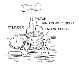
Installing piston in engine.
As you install each piston in the cylinder, install the connecting rod cap and tighten it snugly to prevent the bearing from turning before you move on to the next piston. Check the connecting rod side play and compare it with the specifications listed in the TM.

Checking connecting rod side play.
Don't forget to tighten the connecting rod cap nuts to the manufacturer's specifications and check the bearing clearance--just as you did with the main bearings. Coat them with engine oil as you do all friction surfaces. When this procedure is finished with each piston, install the oil pump.
preventing damage to the crankpin.
OIL PUMP AND OIL PAN INSTALLATION
- dentify how the engine is prepared before the installation of an oil pump.
- Identify the oil pan bolt tightening sequence.
1. Oil Pump Installation
After you have checked the oil pump, prime the pump with the appropriate engine oil by pouring engine oil into the oil pump inlet until the oil flows from the outlet valve. Once you have primed the oil pump, install it according to the appropriate TM.
2. Oil Pan Installation
You are now ready to install the oil pan. Place all gaskets on the oil pan in their proper position and use sewing thread or a fine string to hold the gasket in position if necessary. This is done by tying the string through several screw holes of the oil pan and oil pan gaskets. On most late model engines, this is not usually necessary. Place the oil pan carefully in position so as not to disturb the position of the gaskets and thread the center screw on each side of the oil pan into the block. This will hold the pan in position while you insert the remaining screws. After you have inserted all of the screws, begin tightening them, using the manufacturer's specifications for proper torque. The first two screws inserted should be the first screws tightened, and you should then work from the center, toward each end, alternating from side to side, and front to rear of the pan. This will cause the gaskets to seat properly and eliminate chances for oil leakage. Rotate the engine back to its upright position.
VALVE AND CYLINDER HEAD INSTALLATION
- Identify the correct procedure for installing each of the following components: the
valves, pushrods, rocker arm shaft, and cylinder head.
- Identify the correct tightening sequence for cylinder head bolts.
You already know that valves are located in the cylinder block of the L-head engine, in the cylinder head of the I-head engine, and in both the block and the head of the F-head engine.
1. Valve Installation
From constant use, valves shape themselves to the valve seat. When reusing old valves, be certain that you install each valve in its original location to ensure proper seating. This holds true for all valves, whether you are installing them in the head or in the block. Insert the valve stem first into the valve guide from the bottom of the head. If the valves are equipped with seals, place the valve spring and valve spring retainer over the valve stem and compress the valve spring into place with the valve spring compressing tool. After compressing the valve spring, insert the valve stem locks. However, in some cases you may find that a sleeve is used. This is placed on the valve stem before the locks. If a valve stem cap is used, it is placed over the end of the valve stem after the locks are in place and the valve spring released. Figure below is an example of valves and their associated components. You might note that the valve stem locks are sometimes referred to as keys. When all valves are installed in the cylinder head, the head is ready to be installed on the cylinder block.
2. Cylinder Head and Pushrod Installation
Now you are ready to install the cylinder head. Since the L-head engine is the simplest of heads to install, let's discuss it first. Inspect your cylinder head gasket. In many cases, you will find one side marked "TOP." Be sure to place the gasket on the cylinder block so that the word "TOP" may be seen. In cases where the gasket is not marked, inspect the alignment of the holes in the block with the holes in the gasket. If the holes are not aligned, you have the gasket inverted, or
bottom side up. Now, place the cylinder head in position over the gasket and insert the cylinder head bolts. Screw the bolts into the cylinder block until they are snug against the cylinder head. You must use a torque wrench to tighten the cylinder head bolts. Check the TM for the proper torque specifications and sequence. Figure 6-8 gives examples of cylinder heads having two and three rows of head bolts. Note the tightening sequence for both.

Typical tightening sequence for cylinder heads.
The installation of the cylinder head on the I-head and F-head engines is the same as that for the L-head up to this point. However, before head installation is considered complete on these two engines, the rocker arms and pushrods must also be installed. The pushrods are inserted through holes provided in the cylinder head. The bottom end of the pushrod must seat in the recess located in the tip of the valve tappet or the engine will not operate and the pushrod will be damaged.
3. Rocker Arm Installation
The next step is to assemble and install the rocker arm shaft as shown in below on the next page. Each component is reassembled in its original position. After reassembly, the rocker arm shaft assembly is placed on the cylinder head then tightened to the manufacturer's specifications located in the TM.
Note: Care must be exercised to ensure that each rocker arm seats on both the valve
stem and the pushrod.

Rocker arm shaft assembled.
After the rocker arm shaft is installed, the valves must be adjusted to the manufacturer's specifications as discussed earlier in the course. This is normally done with the engine at normal operating temperature; however, you can make a cold adjustment initially without the engine operating. This will make the hot adjustment easier and quicker. The last items to be installed should be the side pan and/or the rocker arm cover. With this done, you have completed the rebuild of the engine and it is ready to be installed in the vehicle for a run-in test after all accessories have been installed. Accessories will be discussed in subsequent courses.
Monday, 25 April 2016
VALVE MECHANISM
The valve mechanism consists of many associated components. The valves, valve springs, rocker arms, and camshaft just to name a few. It is important to conduct a thorough inspection of each component. The failure of just one valve spring can have an impact on the engine's performance.
1. Valve Inspection and Repair
Begin the repair of the valve mechanism by repairing the valves. Clean the valves thoroughly with a wire brush or buffing wheel to remove all carbon and varnish. When this is done, inspect the valves for pitting, burnt surfaces, scoring, stem warpage, wear, and cocked condition. When you have determined that the valve is serviceable or have replaced it with a new one, check the valve face runout. This is necessary to determine whether the valve will form a pressure- and vacuum-tight seal with the valve seat. To perform this check, use the Prussian blue dye as explained here.
2. Valve Spring Inspection and Repair
To ensure that the valve seats properly, forming a pressure and vacuum tight seal, you must not only have a lapped fit between the valve and seat, but a valve spring of the proper pressure and squareness. To measure the pressure, use a spring tester has pictured below.

Checking valve spring pressure.
If the valve spring is at the specified height, check the spring strength on a pressure gage and compare it with manufacture's requirements in TM. If the valve spring has become weak, discard it and obtain a new one. To determine valve spring squareness, simply place a square alongside the valve spring in the vertical position and measure the point of greatest distance between the two. Valve springs are not repairable; therefore, just as the case with the weak spring, the spring must be replaced. Now, you are ready to install the valves in the cylinder head or in the cylinder block, as the case may be. Insert the valve stem into the valve guide from the combustion chamber side of the head and place the valve spring over the end of the valve stem. Now place the valve spring retainer on the valve spring and attach the valve spring compressor in the same position as when you were removing the valves. Compress the valve spring and insert the valve stem locks. Release the valve spring compressor and the valve is installed. With the valve installed, there is still one check which must be made, the "installed height" of the valve spring. This is done by placing a machinist's alongside the valve spring. Check your measurement against the tolerance listed in the TM. If the installed height does not meet specifications, either the valve or the valve seat insert must be replaced.

Checking valve spring installed height.
Note: If you are repairing an L-head engine, the procedure is the same as outlined on previous page except you will be working with the engine block instead of the cylinder head.
3. Valve Train Inspection and Repair
Unlike the L-head engine, the I-head and F-head engines are equipped with rocker arms which directly activate the valves. Of course, the F-head engine also has valves in the block as well as the head. The in-block valves are not activated by rocker arms. If rocker arms are used, there are a number of components required to operate them. These components make up the "valve train" and each must be inspected and repaired as necessary. Let's begin with the rocker arm shaft assembly, which consists of a hollow shaft with a series of
rocker arms, shaft supports, and springs. To inspect and repair the rocker arm shaft, first disassemble it. Mark the rocker arms to identify their position on the shaft. They should not be interchanged. Now, remove the cotter pin or
other retaining device from each end of the shaft and remove the rocker arms, rocker arm supports, and springs simultaneously. Check the adjusting screws in the rocker arms for damage or excessive wear. Remove the screws ONLY if they need to be replaced. If you will recall from earlier discussion, wear between the rocker arm and the rocker arm shaft will make it necessary to adjust the valves more often than normal. Therefore, before reassembling the shaft, check for this wear. If you can see wear on the shaft or in the bore of the rocker arm, then you know the defective part must be replaced. If not, measure the outer diameter of the shaft and the inner diameter of the rocker arm bore. These measurements are taken with T-gage (telescopic) and micrometer. Check your measurements against the maximum wear limits in the TM. If equipped with locating springs, ensure that none are broken and make sure that the ends of the oil tubes are not split. If everything is in good shape, reassemble the rocker arm shaft and move on down the valve to the valve train to the pushrods. Check the ends of the pushrods for nicks, scores, burrs, and apparent excessive wear by cleaning them thoroughly and giving them a good visual inspection. Check them for a bent condition also. In some cases, nicks, scores, and burrs can be corrected with an oil stone. A bent pushrod must
be replaced. Valve tappets cannot be repaired. Therefore, if the tappet is damaged or excessively worn, it must be replaced. Damage can be checked by visual inspection as can excessive wear on the bottom of the tappet.
4. Camshaft Inspection and Repair
Clean the camshaft in cleaning solvent and blow all oil passages clear with air pressure hose. Check the machined surfaces of the camshaft for nicks, scoring, burrs, and excessive wear. Eliminate all defects possible with crocus cloth or a smooth stone. If you cannot eliminate defects, the camshaft must be replaced. Next check the cam lobe lift. Place the camshaft in a set of "V" blocks and attach a dial indicator. Turn the camshaft until the dial indicator plunger rests on the lowest part of the lobe. Now, set the dial indicator at zero and turn the camshaft until the plunger rests on the highest point of the lift. Compare your reading to the specifications in the TM. If the lobe lift on all lobes does not
meet specifications, replace the camshaft with a new one. The camshaft is checked for runout by placing the dial indicator plunger on the center camshaft main bearing journal. This test is to ensure that the camshaft is in proper alignment to minimize bearing wear. The TM lists the allowable limits of runout. Defective camshafts must be replaced. Another check which must be made before installing the camshaft is the camshaft bearing running clearance. The inner diameter of the bearing bore is measured with the bearing installed. The procedure is the same as was used to remove the bearings. MAKE SURE THE OIL PASSAGE HOLE POSITION IS MARKED. Align the hole of the bearing with the mark and draw the bearing into position. After installing the bearings, measure the inner diameter of the camshaft bearings with a T-gage and micrometer. Now, measure the outer diameter of the camshaft main bearing journals on the camshaft. If they are within acceptable limits according to your TM, you are ready to reassemble the engine. Remember that the running clearance (the difference between the bore measurements and the journal measurement) must be within manufacturer's allowable limits. The outer diameter of the journals is measured with a micrometer as were the piston pin, crankshaft journals, etc.
CYLINDER HEAD
The cylinder head from an L-head engine dose not require major disassembly. Therefore the disassembly portion of this study unit refers mostly to the I-head and F-head engines. The cylinder head is cleaned and inspected just as the engine block was; therefore, it is unnecessary to go into a detailed description. Let's get right to inspection and the repair of the cylinder head.
1. Cylinder Head Inspection and Repair
Begin disassembly by removing the valves. With a valve spring compressing tool compress the valve spring and remove the valve stem locks. There are various types of valve spring compressors. The one described is one of the more common. The spring is compressed by placing the solid end of the compressing tool on the valve head and
the split end of the spring retainer, then compress it with the lever located on the tool. Once this is accomplished, you can easily remove the valve stem locks with your fingers. Cup
your hand over the end of the spring now and release the lever. The valve spring and its related parts are then removed by hand. The valve may also be removed from the bottom side of the cylinder head by hand. Keeping each valve and its related components together, lay them out on a clean surface and carefully inspect each piece for damage.

Valves and related parts.
Now, remove the coolant outlet connection and check the thermostat operation. To remove the outlet connection, simply remove the cap screws retaining it and lift it from the head. Remove the thermostat and drop it into boiling water to check its operation. The thermostat should open. Remove the expansion plugs and replace them as you did in the engine block. Check the head for nicks, burrs, and cracks. Smooth any nicks and burrs with oil stone. A cracked head may be sealed in some cases. The cylinder head is now ready for specification checks. The flatness check is performed to ensure that the head is not warped. This check is made in the same manner as the cylinder head gasket surface of the cylinder block. A straight edge and a feeler gage are used to determine the amount of warpage. Figure below is a good illustration of how to perform the checks.

Checking cylinder head flatness.
Figure shows where these checks should be made. The lines drawn across the surface indicate the positions in which the straight edge should be placed for checking. If you were
working on a cylinder head from an L-head engine, this is the only check you would be required
to make.

Positions for checking cylinder head for flatness.
If the results of the check reveal that the cylinder head warpage exceeds the tolerances listed in the TM, you must have the head ground to obtain a new, flat surface. In some cases, the head may have already been ground as far as allowed and in other cases, heads are manufactured in such a design that they cannot be ground at all. In these cases, discard the cylinder head and obtain a new one through the supply system.
2. Valve Seat Inspection and Repair
Your first step would be a visual inspection. It is important that the valve seat be of the proper width to ensure an air-tight seal and proper valve cooling. Although the entire surface of the valve seat is machined smooth, only a small portion of that surface is actually contacted by the valve when it is closed. If the head is equipped with cast in seats, improper fit or damaged seats would need to be ground (refaced). Grinding requires the use of a electric drill motor and grinding stones of various degrees of angle. Consult the appropriate TM for the proper angle.

Grinding valve seats.
Care must be exercised to prevent the grinding of too much metal from the surface of the seat.
Check contact surfaces between the valve and valve seat by applying a light coat of Prussian blue
dye to the valve face. Lower the valve stem into the valve guide and let the valve drop against the
valve seat. Apply pressure valve head until valve face makes good contact with valve seat, BUT
DO NOT ROTATE. Push up on valve stem until valve face is about one inch above valve seat.
Drop valve back into valve seat and reapply pressure to valve head. Repeat this procedure several
times to get a good imprint in the Prussian blue dye. Being careful not to smear the dye, remove
valve. The imprint in Prussian blue dye should have an even seat mark all the way around the
center of the valve face. If the head you are working on has replaceable seats (valve seat inserts), badly damaged seats
must be replaced. Remove and replace valve seat inserts as illustrated in figure A and B.

A. Removal of valve seat inserts. B. Replacement of valve set inserts.
After valve seats have been replaced, perform a runout check. The valve seat runout check ensures that the seat is perfectly round. This is accomplished by the use of a dial indicator type gage known as a runout gage. The gage manufacturer provides instructions for its use, but basically, you insert the base of the gage into the valve guide, adjust the measuring device to seat on the contact surface of the valve seat, and run the measuring device around the valve seat. The maximum reading reached on the dial indicator tells what the runout is. The runout is then checked against the tolerance listed in the TM.

Checking valve seat runout.
3. Valve Guide Inspection and Repair
Although you may have repaired or replaced the valve seats, the valves will not seat properly unless the valve stem clearance is correct. Check the valve stem clearance now to help ensure proper valve seating. Measure the inside diameter of the valve guide with a telescopic gage and the outside diameter of the valve stem with a micrometer. To obtain valve-to-guide clearance, subtract valve stem diameter from valve guide diameter. Check appropriate TM for proper specifications. If the reading you have obtained is greater than the tolerance, either the valve or the valve guide
must be replaced. Check the condition of both and determine which needs replacement. In some cases, both may have to be replaced. If the cylinder does not have replaceable guides, ream the guide and use an oversized valve. If the engine is equipped with replaceable valve guides and a visual inspection reveals that the valve guide is damaged beyond repair, it must be replaced. To replace the valve guide, the old guide must be driven out of the cylinder head or cylinder block and a new one driven in. This is accomplished by placing the valve guide remover inside the valve guide and drive the guide out through the cylinder head with a ballpeen hammer. When installing valve guides, use the appropriate valve guide installer tool and press.
Position valve guide squarely on guide bore and gently press guide into bore. The installer will position guide to the correct depth.

Installing valve guides.
This should complete the repairs of the cylinder head, or in the case of the L-head engine, the cylinder block. The final component to be repaired is the valve mechanism.
Subscribe to:
Posts (Atom)