1. Piston Removal Preparation
There is quite a bit of work to be done before you can actually remove a piston assembly. The first thing to do is check the connecting rod side play. This is done by inserting a feeler (thickness) gage between each connecting rod bearing cap and its crankshaft throw. Try several leaves of the gage, if necessary, until you find one that can be inserted with a slight drag. Record the number stamped on that leaf. After all connecting rods have been checked, find the side play specifications in your TM and list the rods that are not within the specified tolerance.

Measuring connecting rod side play.
2. Cylinder Ridges
Turn the engine upright again and take a look at the cylinders. Around the very top you can see or feel a ridge. This ridge is produced by carbon deposits and ring wear because the rings do not travel this high. The rings of the piston cause wear on the cylinder as they travel up and down. The top edge of the rings also wears to a curved shape. The ridge at the top of the cylinder will match the shape of the top edge of the ring. When new rings are installed, they have no wear and will strike the ridge, causing ring and, possibly, cylinder wall and piston damage.

Result of installing new pistons rings with ridges at the top of the cylinder
3. Cylinder Ridge Removal
The ridges at the top of the cylinders must be removed before installing new piston rings and now is the best time to do this. By removing the ridges at this time, you eliminate the chance of damage to the piston when it is removed. You will use a tool known as a ridge reamer to remove the ridges. Turn the crankshaft until the piston of the cylinder about to be reamed is at BDC. Now, get a clean cloth and place it inside the cylinder to catch ALL metal filings that might fall into the cylinder. If they are not caught, these filings can cause cylinder wall scoring. While reaming, be very careful NOT to cut into the ring travel area of the cylinder. This will not only damage the cylinder wall but the piston as well. Before turning the crankshaft to bring the next piston to BDC, BE SURE that ALL metal filings are removed and discarded.
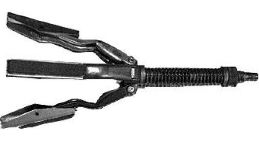
Ridge reaming tool.
4. Piston Removal Procedures
When all cylinders have been reamed, you are ready to remove the piston assemblies. Again, turn the engine upside down. The connecting rod caps and pistons must be removed one at a time to prevent damage to the engine. Turn the crankshaft until the piston to be removed is at BDC. Remove the two cap nuts and lift the cap from the crankpin. Check the cap and the rod to make sure they are marked. If they are not marked, mark the caps and rods with a number stamp or center punch. If a center punch is used, place the number of dots that coincides with the cylinder number. For example, the cap and rod for the #3 cylinder would have three dots. Place all markings ON THE SAME SIDE, numbering them in cylinder number sequence starting with the forward cylinder. This is done so that when the pistons are reinstalled, they will be in the same cylinder and in the same position. Using a hammer handle, push on the end of the connecting rod, forcing the piston up and out the top of the cylinder.

Removing the piston assembly.
Caution: If the ridges are not removed at this time, extra force will be required. Chances are 99 out of 100 that the hammer will slip and cause the connecting rod to strike the crankpin or cylinder wall.
Note: Most pistons are marked at the factory with a notch or arrow, so check each piston first. If the pistons are not marked, as each piston is removed, mark the forward piston with a center punch, numbering them as you numbered the rods.
1.Timing Gear Removal Preparation
To remove the timing gears, you must first remove the crankshaft damper and pulley, the timing gear cover, and the crankshaft oil slinger. After these items are removed, make sure that the timing gears are in good condition. If you do not check them now, you cannot check them until they are reinstalled during reassembly, and this may mean extra work if you have to change them after reinstallation.
2. Timing Gear Tests
The first check to make is for free play (backlash) between the gears. If the backlash is excessive, the valves will open and close later than they should. For this check, use a dial indicator. The instrument is placed on the cylinder block or, depending on the manufacturer's design, attached to the cylinder block so that the dial plunger rests on the face of one gear tooth of the camshaft gear. When making this adjustment, be sure that the teeth of the two gears are in firm
contact and that the dial reads zero. Now, turn the camshaft gear just enough to cause it to touch the next tooth on the crankshaft gear. Record the reading on the dial indicator and make the next check.

Checking timing gear backlash
Before removing the timing gears, make one more check, the camshaft end play. This will determine if it will be necessary to replace the camshaft thrust bearing. Although this check has no direct connection with the condition of the timing gears, it can be made only with the camshaft gear installed.
With the dial indicator base in the same position, place the plunger on the end of the camshaft gear retainer bolt. Now, place the end of the pry bar between the gear and the engine block and gently pry the gear away from the engine. Record the dial indicator reading. With all the checks done, check your readings against the specifications in the TM for your vehicle. If the gear backlash or runout is beyond tolerance, the gears must be discarded. If the camshaft end play is excessive, this means you will have to replace the camshaft thrust bearing before reinstalling the camshaft.
3. Timing Gear Removal
Now, you can remove the timing gears. The crankshaft gear is removed first to prevent damage to the camshaft gear. If you remove the camshaft gear first, you will be turning the gear puller in a clockwise direction while the camshaft gear is attempting to rotate in a counterclockwise direction due to the design of the gear teeth. This causes added resistance to the puller. Install the crankshaft damper retaining bolt before installing the gear puller. If the gear puller is installed without the retainer bolt, thread damage will result. After the gear puller is installed, simply turn the center bolt of the puller clockwise while holding the gears to prevent them from turning. The TM for the vehicle will instruct you as to the best method for holding the gears. Removal of the camshaft gear is accomplished with the same tool. The retaining bolt, while still attached, is loosened a few turns before installing the puller. Install the puller basically the same way you did for crankshaft removal. Turn the puller clockwise, allowing the gear to break free of the camshaft. The puller then may be removed, the retainer bolt removed, and the gear lifted from
the camshaft.
No comments:
Post a Comment