Introduction. After all machining procedures on the cylinder block have been performed correctly, the engine is ready for reassembly. Let's not forget that while assembling the
engine, specifications are still just as important as they were during the repair of the individual components. Remember also that dirt is harmful to the engine. Even the slightest particle is abrasive and can shorten the life of the engine by many miles or hours of operation. With the above facts firmly in mind, you are ready to assemble the engine with which you have taken so much care to repair properly.
CRANKSHAFT INSTALLATION
1. Preassembly
To ensure proper lubrication of moving parts, all bearings, shafts, and contact surfaces must be lubricated before installation and engine oil should be used for this. Never reuse old gaskets and seals. Once a seal has been removed, it is damaged and damaged seals can be a source of leakage that results in premature wear and damage to moving parts. During assembly of the engine, almost every nut and bolt to be tightened has a specific torque. These torque specifications are listed in the TM and must be strictly adhered to. Over-tightened bolts and nuts will result in excess stress on the metal, and under-tightened nuts and bolts will result in oil or vacuum and pressure leaks. Basically, all engines are assembled in the same manner. This study unit provides a basic knowledge of assembly, and your TM will provide you with details of the particular engine you will be rebuilding or repairing.
2. Installing the Crankshaft
The crankshaft is the first component that must be installed if the engine is to be assembled in a logical order. This may vary depending on the type of engine you are rebuilding. Before actually placing the crankshaft in the engine, position the engine block with the crankshaft side up. Install the rear main bearing seals (the rear main bearing is the only main bearing with seals). These seals are installed in grooves provided to the rear of the point from which the rear main journal of the crankshaft rests in the engine and on the groove provided in the rear main bearing cap. There are various types of seals (felt packing, neoprene, encased, etc.). common types of rear seals.

Encased seal

Two-piece seal
The encased seal is installed after the crankshaft has been installed in the engine. Care must be exercised to ensure that the seal is driven into the block evenly, or damage may result. To install the crankshaft, first install the upper halves of the crankshaft's main bearings in the engine block, and the lower halves in the main bearing caps. Make sure the bearing halves are thoroughly cleaned and, as mentioned previously, all friction surfaces coated with engine oil. The bearing tangs must fit into the slots in the cap and block evenly, or they will be flattened. The tang is provided to prevent the bearing from turning with the crankshaft. If a bearing turns, it will cause almost immediate damage.

Installing main bearing halves.
With all bearings in place, lower the crankshaft into the block carefully so that no parts are damaged. Though not always necessary, it is usually best to install the woodruff key and crankshaft timing gear before installing the crankshaft in the block. To hold the crankshaft in place, you must install all the bearing caps. First, install the front main bearing cap. Place the front main bearing in its position. Some manufacturers recommend lubricating the threads of the bearing cap bolts before installation and torqueing. Tighten the bearing cap bolts until the caps fit snugly. Once this has been done, center the crankshaft thrust bearings and tighten them according to manufacturer's recommendations. Consult the specific TM for the engine in question. Remember, when tightening components to torque specifications, do NOT apply full torque immediately. With a torque wrench, tighten one side to five or ten pound-feet, then tighten the other side
equally. Switch back to the first bolt and repeat the procedure until both bolts are tightened to manufacturer's specifications.
When the bearings are installed, the crankshaft must be checked for end play just as you did before removing the crankshaft during disassembly. With this done and with problems corrected by installing another crankshaft thrust bearing if necessary, the crankshaft installation is now completed and you can install the camshaft and tappets.
1. Installing the Valve Tappets, Camshaft and the Camshaft Timing Gear
Install the camshaft first, then insert the tappets into their bores. If you reuse the valve tappets, make sure that they are reinstalled in their original bores. Install the woodruff key and camshaft timing gear on the camshaft and insert the camshaft into its position from the front of the engine. Be careful to ensure that all machined surfaces have been coated with engine oil and that they are not damaged during installation. When meshing the crankshaft and camshaft timing gears, make sure that the timing marks are positioned according to the manufacturer's specifications in the TM, and number one position is at TDC. Install the thrust plate bolts.

Positioning timing marks on the camshaft and crankshaft
2. Timing Gear Tests
With the timing gears in place but before completing the installation of the camshaft, perform the same checks that you performed before you removed the shaft. Do you remember what those checks were? The two checks that must be performed on the camshaft are backlash (the measurement of the amount of freeplay between the gear teeth, and camshaft end play which determines if the thrust
bearing has excessive free play. If you are not familiar with the procedure for performing these tests, refer to Study Unit 4, Engine Disassembly, Timing Gear Tests to refresh your memory.
FLYWHEEL AND PILOT BEARING INSTALLATION
LEARNING OBJECTIVES
- Identify the test performed on the flywheel.
- Identify the assembly procedure for installing the two types of pilot bearings.
1. Flywheel Installation
The installation of the flywheel is relatively simple. Position the flywheel on the rear of the crankshaft and install the flywheel retaining bolts. Keep in mind that not all flywheels are the same. Tighten the bolts to manufacturer's torque specifications, in sequence, and according to the appropriate technical manual (TM). When the flywheel retaining bolts have been tightened, you must perform a flywheel runout test to ensure that the flywheel is not warped. If the flywheel is warped, what effect will this have on clutch operation? If you cannot answer this question, refer back to Study Unit 4 to refresh your memory.
2. Pilot Bearing Installation
A pilot bearing is one of two types: a ball bearing or a bushing. Some bearings are installed in the end of the crankshaft, while others are installed in the center of the flywheel. Both types are installed by simply driving them into their respective position with a bearing installer or a soft metal drift, such as a brass drift. However, they must be driven in evenly. Before installation, the bore in which the bearing fits should be coated with a light film of grease.
of pilot bearings are ball and
bushing. In the next lesson, you'll learn about piston installation.
PISTON INSTALLATION
- Identify the procedure to prevent damage to the crankpin during piston installation.
- Identify the tool used to compress the rings on a piston before piston installation.
1. Piston Preparation
You can now begin installing the pistons. The piston is installed from the top of the cylinder, which can present a problem. If, while installing the piston, the shoulders of the connecting rod saddle strike the crankpin of the crankshaft, nicks, scratches, and burrs may result. This may be prevented by installing the connecting rod bearing cap bolts in the connecting rod before installation, and installing a rubber hose on the bolts.

Rubber hose installed on connecting rods to protect crankpin
The rubber hose may be a vacuum hose or any small hose that will fit snugly over the bearing cap bolts. The hose should be thick enough so that the outer edge of the hose is flush with the inner shoulders of the connecting rod saddle. To further prevent damage, check the connecting rod saddle to ensure that the shoulders are in perfect alignment with the crankpin. Most pistons are notched or marked in some manner to indicate the front of the piston. Make sure that the mark is positioned toward the front of the engine.
2. Piston Installation
The tool illustrated in figure 6-6 is a ring compressor. It is installed on the piston before installation. The ring compressor compresses the rings around the piston so that they do not bind against the top edge of the cylinder. After the ring compressor is installed on the piston, position the piston on top of the cylinder opening. Push or tap the piston gently into the cylinder until the connecting rod saddle seats on the crankpin. To do this, the rotate the crankshaft until the crankpin of the cylinder in which you are installing the piston is at BDC (bottom dead center).
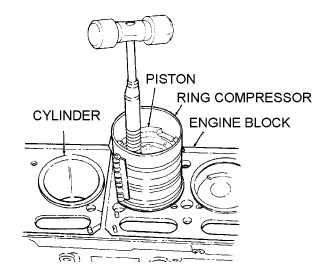
Installing piston in engine.
As you install each piston in the cylinder, install the connecting rod cap and tighten it snugly to prevent the bearing from turning before you move on to the next piston. Check the connecting rod side play and compare it with the specifications listed in the TM.

Checking connecting rod side play.
Don't forget to tighten the connecting rod cap nuts to the manufacturer's specifications and check the bearing clearance--just as you did with the main bearings. Coat them with engine oil as you do all friction surfaces. When this procedure is finished with each piston, install the oil pump.
preventing damage to the crankpin.
OIL PUMP AND OIL PAN INSTALLATION
- dentify how the engine is prepared before the installation of an oil pump.
- Identify the oil pan bolt tightening sequence.
1. Oil Pump Installation
After you have checked the oil pump, prime the pump with the appropriate engine oil by pouring engine oil into the oil pump inlet until the oil flows from the outlet valve. Once you have primed the oil pump, install it according to the appropriate TM.
2. Oil Pan Installation
You are now ready to install the oil pan. Place all gaskets on the oil pan in their proper position and use sewing thread or a fine string to hold the gasket in position if necessary. This is done by tying the string through several screw holes of the oil pan and oil pan gaskets. On most late model engines, this is not usually necessary. Place the oil pan carefully in position so as not to disturb the position of the gaskets and thread the center screw on each side of the oil pan into the block. This will hold the pan in position while you insert the remaining screws. After you have inserted all of the screws, begin tightening them, using the manufacturer's specifications for proper torque. The first two screws inserted should be the first screws tightened, and you should then work from the center, toward each end, alternating from side to side, and front to rear of the pan. This will cause the gaskets to seat properly and eliminate chances for oil leakage. Rotate the engine back to its upright position.
VALVE AND CYLINDER HEAD INSTALLATION
- Identify the correct procedure for installing each of the following components: the
valves, pushrods, rocker arm shaft, and cylinder head.
- Identify the correct tightening sequence for cylinder head bolts.
You already know that valves are located in the cylinder block of the L-head engine, in the cylinder head of the I-head engine, and in both the block and the head of the F-head engine.
1. Valve Installation
From constant use, valves shape themselves to the valve seat. When reusing old valves, be certain that you install each valve in its original location to ensure proper seating. This holds true for all valves, whether you are installing them in the head or in the block. Insert the valve stem first into the valve guide from the bottom of the head. If the valves are equipped with seals, place the valve spring and valve spring retainer over the valve stem and compress the valve spring into place with the valve spring compressing tool. After compressing the valve spring, insert the valve stem locks. However, in some cases you may find that a sleeve is used. This is placed on the valve stem before the locks. If a valve stem cap is used, it is placed over the end of the valve stem after the locks are in place and the valve spring released. Figure below is an example of valves and their associated components. You might note that the valve stem locks are sometimes referred to as keys. When all valves are installed in the cylinder head, the head is ready to be installed on the cylinder block.
2. Cylinder Head and Pushrod Installation
Now you are ready to install the cylinder head. Since the L-head engine is the simplest of heads to install, let's discuss it first. Inspect your cylinder head gasket. In many cases, you will find one side marked "TOP." Be sure to place the gasket on the cylinder block so that the word "TOP" may be seen. In cases where the gasket is not marked, inspect the alignment of the holes in the block with the holes in the gasket. If the holes are not aligned, you have the gasket inverted, or
bottom side up. Now, place the cylinder head in position over the gasket and insert the cylinder head bolts. Screw the bolts into the cylinder block until they are snug against the cylinder head. You must use a torque wrench to tighten the cylinder head bolts. Check the TM for the proper torque specifications and sequence. Figure 6-8 gives examples of cylinder heads having two and three rows of head bolts. Note the tightening sequence for both.

Typical tightening sequence for cylinder heads.
The installation of the cylinder head on the I-head and F-head engines is the same as that for the L-head up to this point. However, before head installation is considered complete on these two engines, the rocker arms and pushrods must also be installed. The pushrods are inserted through holes provided in the cylinder head. The bottom end of the pushrod must seat in the recess located in the tip of the valve tappet or the engine will not operate and the pushrod will be damaged.
3. Rocker Arm Installation
The next step is to assemble and install the rocker arm shaft as shown in below on the next page. Each component is reassembled in its original position. After reassembly, the rocker arm shaft assembly is placed on the cylinder head then tightened to the manufacturer's specifications located in the TM.
Note: Care must be exercised to ensure that each rocker arm seats on both the valve
stem and the pushrod.

Rocker arm shaft assembled.
After the rocker arm shaft is installed, the valves must be adjusted to the manufacturer's specifications as discussed earlier in the course. This is normally done with the engine at normal operating temperature; however, you can make a cold adjustment initially without the engine operating. This will make the hot adjustment easier and quicker. The last items to be installed should be the side pan and/or the rocker arm cover. With this done, you have completed the rebuild of the engine and it is ready to be installed in the vehicle for a run-in test after all accessories have been installed. Accessories will be discussed in subsequent courses.
No comments:
Post a Comment